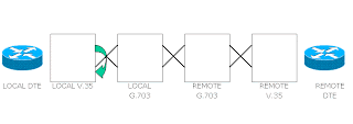
3. TROUBLESHOOTING
3.1 LOOP TEST
Loop test is performed to check the physical connectivity of the link.
Two types of loop test are available they are
1. Hard loop
2. Soft loop
3.1.1 Hard Loop
This loop is given using physical media. This can be classified into two types
a. 2 Wire Loop
b. 4 Wire Loop
3.1.1.1 2 WIRE LOOP
This loop is used to test a single pair of wire.
This test can be performed to check both towards router end as well as near end exchange. When given towards router end the interface will in looped status.
4 WIRE LOOP
This loop is used to test a four-wire circuit.
This test can be performed to check both towards router end as well as far end exchange till customer end router. When given towards router end the interface will in looped status.
SOFT LOOP
This loop is given using active equipments namely V.35 modem and G703 modems.
V.35 MODEM LOOP
There are three types
1. Local
2. Remote
3. Digital
LOCAL LOOP
Used to check the connectivity between local DTE interface and local V.35 Modem
REMOTE LOOP
Used to check the circuitry till near end G703
DIGITAL LOOP
Used to check end-to-end connectivity till far end router interface.
G703 MODEM LOOP
There are two loops
1. Local
2. Remote
LOCAL LOOP
To check the connectivity towards far end router interface.
REMOTE LOOP
To check the connectivity between local G703 and near end router interface
TROUBLESHOOTING
There are many parameters that need to be considered when troubleshooting a leased line. They are
1. CRC Error Check
2. Reliability
3. Collision
4. Interface Reset
5. Other parameters
CRC ERROR CHECK
The CRC(Cyclic Redundancy Check) is a very powerful but easily implemented technique to obtain data reliability. The CRC technique is used to protect blocks of data called Frames. Using this technique, the transmitter appends an extra n- bit sequence to every frame called Frame Check Sequence (FCS). At the receiving end, validity of data is checked using the same n- bit sequence
CRC combines three advantages:
1. Extreme error detection capabilities.
2. Little overhead.
3. Ease of implementation.
In a router interface, CRC errors denote the number of invalid bits being transferred. CRC errors occur when CRC calculation does not pass-indicating the data has been corrupted due to one of these following reasons:
1. Noisy serial line.
2. Serial cable is too long.
3. CSU line clock is incorrectly configured.
The solution to CRC error problem can be any one of the following:
1. Ensure that the line is clean enough for transmission requirements. Shield the cable if necessary.
2. Make sure that the cable is within the recommended length.
3. Ensure that all the devices are properly configured for a common line clock
CRC will be 0 in a link that is up and working well. If there is a problem in a link, CRC will have a positive value.
RELIABILITY
Reliability is the probability that a link will perform its prescribed duty without failure for a given time when operated correctly in a specified environment.
Reliability means
1. Maximum availability - works first time, every time
2. Predictable performance any time of the day
In a router interface, it is calculated as an exponential average over 5 minutes
COLLISION
Collision is the result of two network nodes transmitting on the same channel at the same time. The transmitted data is not usable. Collision value will be 0 when the line is up and working fine. When collision has a positive value, it implies there is some problem in the link.
INTERFACE RESET
It is the number of times an interface has been completely reset. This can happen if packets queued for transmission were not sent within several seconds time. On a serial line, this can be caused by a malfunctioning modem that is not supplying a transmit clock signal, or by a cable problem. If the system notices that the carrier detect line of a serial interface is up but the line protocol is down, it periodically resets the interface in an effort to restart it. Interface resets can also occur when an interface is looped back or shut down. This parameter is used to indicate the fluctuations in the leased line link. It has a positive value set in it in case of any fluctuations, else has a value zero when the link is working fine.
OTHER PARAMETERS
The other parameters that can be looked for when solving a problem in a leased line are:
1. RTS and CTS
2. DCD
3. DSR
4. DTR
RTS AND CTS
When two stations need to communicate with each other, the sender of the message sends a Request To Send (RTS) message. Only when the receiver sends a Clear To Send (CTS) message back to the sender, actual communication starts.
For eg: If a station, say A wants to send a data frame to station B, station A first sends a request-to-send (RTS) frame. If station B receives the RTS frame, then B issues a clear-to-send (CTS) frame. All stations within range of B receive the CTS frame and are aware that A has been given permission to send, so they remain quiet while station A proceeds with its data frame transmission. If the data frame arrives without error, station B responds with an ACK. This is illustrated in the following diagram
DATA CARRIER DETECT (DCD)
Data Carrier detect (DCD) refers to the number of times the carrier detect signal of a serial interface has changed state. For example, if data carrier detect (DCD) goes down and comes up, the carrier transition counter will increment two times. It also indicates modem or line problems if the carrier detect line is changing state often.


